Digital Threeway Valve
The Digital Threeway Valve is an automation symbol for a valve that connects three pipes, where each port is either open or closed, such as an on/off diverting or mixing valve. It is found in the Automation - OpenBridge section of the Perspective Component Palette as Valve - Threeway Digital (Experimental). It is a palette entry of its own, listed right after the Valve, which is for two-port valves only.
Note: This component is experimental: its properties may change in a later version.
It is meant to be placed in a mimic or diagram, typically in a coordinate container, with its properties bound to the state of the device. The Digital Threeway Valve shows the state it is given; it does not change it, and clicking it does nothing unless you configure an event.
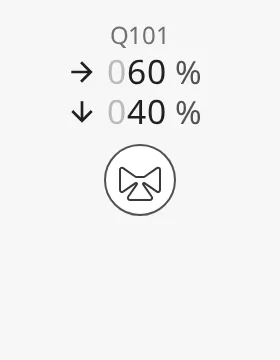
The Digital Threeway Valve is one of the automation buttons. The readout and tag, the alert frame, the progress ring, the badges, the size and the positioning are shared by all of them and are described in Automation Buttons — Common Features. This page covers what is specific to the Digital Threeway Valve. For a valve with continuously opening ports, use the Analog Threeway Valve; for a two-port valve, the Digital Valve.
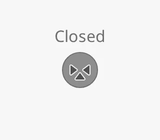
A Digital Threeway Valve dropped from the palette with default properties (all ports closed):
The valve has three ports and one side without a port. Bind open1, open2
and open3 to whether each port is open (true) or closed (false).
The ports are numbered from the side without a port, in the order left, stem,
right as seen with the stem pointing down. With the default
orientation bottom, port 1 is the left port, port 2 the
bottom port (the stem) and port 3 the right port. Port 2 is always the
stem; the numbering turns with the symbol.
What the symbol shows:
- Fewer than two ports open — no flow can pass, so the valve is drawn closed (filled and grey) and the readout shows Closed. A single open port is drawn the same as no open port.
- Exactly two ports open — the closed port is drawn plugged (filled).
- All three ports open — the open symbol.
In a Connector Diagram, the medium flows only between the ports that are open, and never through the side without a port.
| All closed | Only 1 open | 1 and 2 open |
|---|---|---|
 |
|
 |
| 1 and 3 open | 2 and 3 open | All open |
|---|---|---|
 |
 |
 |
Properties
Section titled “Properties”| Name | Description | Property Type |
|---|---|---|
| open1 | Whether port 1 is open. Default false. |
value |
| open2 | Whether port 2, the stem, is open. Default false. |
value |
| open3 | Whether port 3 is open. Default false. |
value |
Orientation
Section titled “Orientation”orientation names the side the stem (port 2) points to: bottom (default)
and top lay the valve on a horizontal pipe, left and right on a vertical
one. The images show ports 1 and 2 open and port 3 closed, so the plugged port
shows where port 3 ends up:
bottom (default) |
left |
top |
right |
|---|---|---|---|
|
 |
 |
 |
Where each port is, per orientation:
bottom— port 1 left, port 2 bottom, port 3 right.left— port 1 top, port 2 left, port 3 bottom.top— port 1 right, port 2 top, port 3 left.right— port 1 bottom, port 2 right, port 3 top.
Flow Readout
Section titled “Flow Readout”Flow through a three-way valve can go several ways at once, so the status row of
the readout is a list, set with flows:
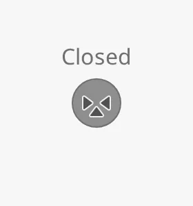
- While no flow can pass (fewer than two ports open), the readout shows
Closed, whatever
flowsholds. - While flow can pass and
flowsis empty (the default), it shows Open. - Otherwise it shows one row per item in
flows.
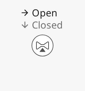
| Closed | Open, no flows |
|---|---|
 |
 |
flows does not follow the ports: the component does not work out where the
flow goes. Bind or write the rows you want to show.
Each item is one of two kinds of row:
- Value row —
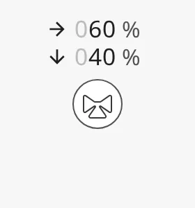
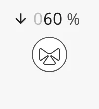
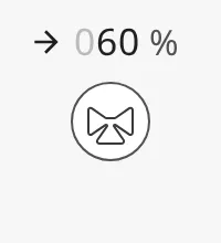
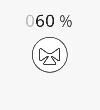
direction,valueandunit. Shows an arrow, the value with three digits (leading zeros greyed out) and the unit.unitdefaults to%. - State row —
directionandopen. Shows an arrow and Open or Closed. Withdirectionnone, the on or off icon is shown in place of the arrow.
A row is a state row as soon as it has an open key. A row added in the
Property Editor starts as a value row (direction none, value 0, unit
%); add an open key to it to make it a state row.
Example: two value rows, flow going right and down:
[ {"direction": "right", "value": 60, "unit": "%"}, {"direction": "down", "value": 40, "unit": "%"}]Example: two state rows:
[ {"direction": "right", "open": true}, {"direction": "down", "open": false}]| Value rows | State rows | State row, no arrow |
|---|---|---|
 |
 |
 |
Direction
Section titled “Direction”direction is the arrow in front of the row, pointing on screen: up, down,
left, right or none (no arrow). It does not turn with
orientation; point it the way the flow goes in your diagram.
up |
down |
left |
right |
none (default) |
|---|---|---|---|---|
 |
 |
 |
 |
 |
Properties
Section titled “Properties”| Name | Description | Property Type |
|---|---|---|
| flows | Readout rows, one per flow. Default [] (shows Open or Closed). |
array |
| flows[n].direction | Arrow in front of the row: up, down, left, right or none. Default none. |
value |
| flows[n].value | Value of a value row. Default 0. |
value |
| flows[n].unit | Unit of a value row. Default %. |
value |
| flows[n].open | Makes the row a state row: true shows Open, false shows Closed. Not present on a new row. |
value |
Variant
Section titled “Variant”variant selects whether the icon is drawn on a button or directly on the
background:
regular(default) — the icon sits on a round button.flat— only the icon is drawn, larger and without a button. Use it where the valve is part of a pipe in a diagram.
| Closed | Open | |
|---|---|---|
regular |
|
|
flat |
 |
 |
Properties
Section titled “Properties”| Name | Description | Property Type |
|---|---|---|
| open1 | Whether port 1 is open. Default false. See Ports. |
value |
| open2 | Whether port 2, the stem, is open. Default false. |
value |
| open3 | Whether port 3 is open. Default false. |
value |
| orientation | Side the stem points to: bottom, left, top or right. Default bottom. |
value |
| flows | Readout rows, one per flow. Default []. See Flow Readout. |
array |
| variant | regular draws the icon on a button, flat draws only the icon. Default regular. |
value |
Common Properties
Section titled “Common Properties”The Digital Threeway Valve is an automation button. The properties below work in the same way on every automation button, and are described in Automation Buttons — Common Features:
- Readout — The readout next to the symbol: the status row (here the flow readout) and the tag name. Properties:
showReadoutStack,readoutPosition,readoutSize,showStatus,showStatusIcon,hasTag,tag. - Positioning — Which part of the button is aligned to the component’s box. Properties:
positioning. - Size — Size of the whole component. Properties:
componentSize. - Activated — Highlighted background that marks the symbol as selected. Properties:
activated. - Static — Grey symbol for a device whose state is unknown. Properties:
static. - Alert Frame — Alert frame around the symbol. Properties:
alert,alertFrameType,alertFrameStatus,alertFrameMode,alertFrameThickness,showAlertCategoryIcon,showAlertIcon,alertIcon,alertLabel,alertTimer. - Progress — Progress ring while a command is carried out. Properties:
progress,progressMode,progressValue. - Badges — Badges in the corners of the symbol. Properties:
badgeControl,badgeAlert,badgeInterlock,badgeCommandLocked. - Style — Standard Perspective style object.
Component Events
Section titled “Component Events”The Digital Threeway Valve has no component events of its own. The standard
Perspective events, such as onClick, are available in the component’s event
configuration. See
Operating a Device.
Found an error or something unclear?
Tell us what is wrong, confusing or missing on this page.
Built on the OpenBridge Design System